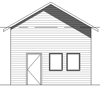
Revit Siding Lines On Elevations

Adding Flair With Flare Architecture Details Revit Architecture Barn Style House

Revit 2017 Tutorials How To Make An Beautiful Elevation In Revit Youtube Revit Tutorial Architecture Architecture Program Revit Architecture

Revit Tutorial Constant Slope Rigging Family Rigid Insulation Revit Tutorial Rigid Insulation Tutorial

Revit Tutorial Creating Exploded Axons Advanced Displaced View Techniques Therevitkid Com Tuto Revit Tutorial Revit Architecture Architecture Graphics

110 Tutorial How To Control Building Elevation Line Weights In Revit Architecture Building Elevation Revit Architecture Architecture

4 Bedroom Farmhouse With Outdoor Living Space Floor Plans Family House Plans Outdoor Living Space

This trick is easy.
Revit siding lines on elevations. New depth cueing feature from revit 2017 changed everything it is now easy to produce beautiful elevations. For the best effect and better performance ensure that far clipping is specified for the view. Normal elevations are plotted using hidden line views and we need to show the siding material. I ve searched for the topic and found lots of advice to use bumps to show the corrugated siding.
Typical reference elevation labels might include north south east west. Stop making boring elevations. I was planning to assign a bmp file file for the realistic view renderings and model hatch pattern for viewing otherwise. About reference elevations label existing elevations to orient a viewer.
For more tips tricks and tutorials on all things revit and bim. Before we go to the revit detailing tools let us find out how we can represent the siding wall in elevation views. Click lighting on the graphic display option menu and set shadows to 15 instead of 80. In the far clipping dialog select clip without line or clip with line and click ok.
This makes the effect more subtle and easier for the eyes. Greg wheler 25 493 views. Cast shadows immediately give your elevation a sense of depth. About custom elevation tags develop elevation symbols and names that fit the needs of your organization.
Remember to use model pattern if you want to show it in 3d too. If you like this. However the default setting is too dark. Open a section or elevation view architectural or coordination discipline only.
We need to create a new material and define the surface pattern. But how can i get it to show properly when viewed in hidden line view. On the properties palette for far clipping click in the value field.

Youtube Scope Box Building Information Modeling Scope Autodesk Revit

Revit Architecture 2011 Tutorial Creating Detail Lines Youtube

Pin On Skool

Elevation Masking Lines Y Exportacion A Photoshop Elevation Floor Plans Presentation

Revit House Plans Download Free Best Of Cool Revit Presentation Plans In 2020 Revit Architecture How To Plan Revit Tutorial

Revit Architecture 2012 Wall Creation Stacked Wall Creation With Brick Below Siding Below Revit Architecture Wall Creations Architecture

Revit Wall Details Youtube

How To Create A Pyramid Shape In Revit Pyramids Shapes Create

Residential Elevation Drawings Google Search House Architecture Design Architecture House Architecture Design

3 Benefits Of Using Revit View Filters Cadnotes Filters Doors And Floors Views

Architectural Drawings Models Photos Etc Archimaps Elevation Of The City Hall Extension Architecture Drawing Architecture Old Classic Architecture

Revit Hiding Linked Model S Grid Level Lines Structural Model Videos Tutorial Levels

Pin On Architectural Cad Blocks

Revit Arch Tutorial Niche Creation Youtube Tutorial Niche Arch

Plan Symbols Floor Plan Symbols How To Plan Architecture Symbols

Autodesk Revit View Scales Ceiling Plan Scale Autocad

Curtain Wall Detail Bing Images With Images Curtain Wall Detail Roof Detail Facade Architecture

Image Result For Floor Plan Roller Blinds Symbol Floor Plan Symbols How To Plan Architecture Symbols
1

Energy Efficient Revit Construction Details Energy Efficient Construction Detailed Drawings Architecture Details

Architectural Terra Cotta Standard Construction Revit Architecture Ancient Architecture Architecture

Revit Software For Mep Autodesk Revit Software Building Information Modeling Engineering Design Process

Reverse Bat And Board Siding Board And Batten Siding Configuration With Images Board And Batten Siding

Trying New Things Elevation Drawing Education Architecture Architecture Elevation

Revit Tutorials Roofs Revit Tutorial Modern Roofing Roofing

Beautiful 3d Modern Elevation Duplex Design Walkthrough By Aastitva Vi In 2020 Duplex Design Revit Architecture Neoclassical Architecture

Interior Elevations Kitchen Freelance Interior Designer Architecture Details Interior

Revit Architecture Modern House Design 6 Youtube

Tracery Kitchencad1 Jpg Jpeg Image 2655x1403 Pixels Scaled 47

3d Contemporary Houses Revit Model House Architecture Design Architecture House Modern Architecture House
Revit Structure Revit Autodesk Building Information Modeling Structural Engineering Software Apps

Gallery Of Paasitorni Hotel K2s Architects 17 Construction Details Architecture Master Room Design Architecture Elevation

Pin On Architectural Cad Blocks

Balkan Architect Youtube Revit Tutorial Building Information Modeling Revit Architecture

Reference View Referenciar Otra Vista O Detalle A Un Callout Life Hacks Autodesk Revit Reference

Gallery Of Sessa Residence J P A 19 Architecture Design Process Architecture Revit Architecture

Wall Detail Section On Pinterest Section Drawing Masonry Veneer Mimari Detaylar Mimari Cizimler Mimari
Revit Repeating Detail Siding Wall

Plan Region In Stairs Jpg 575 378 How To Plan Stairs Architecture Plan

Corner Monolithic Stair Illuminati Stairs Corner

Pin On Architectural Cad Blocks

Elevation And Ground Floor Details Of Bus Terminal Design Dwg File Cadbull In 2020 Bus Terminal Ground Floor House Siding

